This product is an economical Ethernet to RS-485 module with a dedicated integrated circuit at its core. It can be used with 9V, 12V or 24V voltages. The half-duplex RS-485 serial port end supports all common combinations of baud rates, stop bits and parity bits, while the 10M Ethernet end not only functions as a MODBUS-TCP to MODBUS-RTU gateway, but also supports traditional transparent transmission protocols. Meanwhile, it can act as a server to accept MODBUS-TCP connections or connect to cloud servers in reverse. All configurations of the module can be set through the on-board USB communication port or the Ethernet port.
Chapter 1: Product Overview
1.1 Introduction
This product is an economical Ethernet to RS-485 module with a dedicated integrated circuit at its core. It is compatible with 5V, 9V, 12V or 24V voltages. The half-duplex RS-485 serial port supports all common combinations of baud rates, stop bits and parity bits, while the 10M Ethernet port can function as a MODBUS-TCP to MODBUS-RTU gateway and also support traditional transparent transmission protocols. Additionally, it can act as a server to accept MODBUS-TCP connections or connect to cloud servers in reverse. All configurations of the module can be set through the on-board USB communication port or the Ethernet port.
During mass production, the internal functions of this product can be fully customized. You can specify the communication parameters you need.
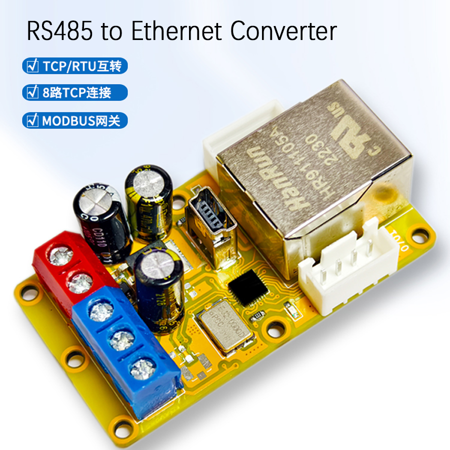
1.2 Structural Description
There are four screw terminals, one standard RJ45 network interface and two indicator lights on the product. The descriptions of each terminal and component are shown in the following figure and table.
Name
Number
Meaning
Power Positive
0
Power positive input, typical current consumption during module operation is 40mA, red.
Power Negative
1
Power negative input, typical current consumption during module operation is 40mA, red.
Differential Positive
2
RS-485 communication differential twisted pair positive (A), blue.
Differential Negative
3
RS-485 communication differential twisted pair negative (B), blue.
USB Interface
4
USB communication interface, will be enumerated as a serial port after connecting to a computer.
Power Indicator
5
Indicator light for power connection status, green.
Communication Indicator
6
Indicator light for RS-485 communication status, red.
Ethernet Port
7
RJ45 interface for network connection, silver.
Sensor Positive
8
Extra 5V 50mA power positive for sensor use, white.
Input/Output 0
9
Extra 3.3V multiplexed input/output port 0, no 5V tolerance, white.
Input/Output 1
10
Extra 3.3V multiplexed input/output port 1, no 5V tolerance, white.
Sensor Negative
11
Extra power negative for sensor use, white.
Sensor Positive
12
Extra 5V 50mA power positive for sensor use, white.
Input/Output 2
13
Extra 3.3V multiplexed input/output port 2, no 5V tolerance, white.
Input/Output 3
14
Extra 3.3V multiplexed input/output port 3, no 5V tolerance, white.
Sensor Negative
15
Extra power negative for sensor use, white.
Chapter 2: Communication Protocols
2.1 Introduction to MODBUS-RTU
This product provides a half-duplex RS-485 serial communication port. It uses two serial differential lines to transmit data: A (negative polarity) and B (positive polarity). Due to the use of differential signal lines in RS-485, data can be transmitted over long distances, reaching several kilometers. By adding repeaters, the transmission distance can be further extended. The two lines of RS-485 are responsible for both receiving and transmitting, making it half-duplex, meaning that receiving and transmitting cannot occur simultaneously. The serial communication parameters of each module on the same RS-485 bus must be the same. To enable normal communication between the upper computer and the module, a communication protocol is also required to standardize the data transmission between them. Here, we use the MODBUS-RTU protocol. MODBUS is an industrial field standard bus proposed by MODICON and has now become one of the preferred choices in industrial control.
In the MODBUS-RTU based on serial port, the default communication format is 1 start bit, 8 data bits, 1 even parity bit and 1 stop bit. Data is in big-endian byte order (BE), that is, the high byte is in front and the low byte is behind. In the ADU, the "address code" is an 8-bit value. To communicate normally with the module, this value should be consistent with the module's setting. 0x00 is a special address for broadcasting. This module responds to this address but does not return data. The final check code is a 16-bit CRC16 check value, and its generating polynomial is fixed at 0xA001. It is worth noting that the transmission of the CRC16 value uses little-endian byte order (LE), that is, the low byte is in front and the high byte is behind. The CRC16 is calculated for the entire ADU including the PDU and address field. All MODBUS-RTU function codes supported by this module are listed in the following sections. Other instructions are not supported.
2.2 Introduction to MODBUS-TCP
This product provides a 10M Ethernet port with an RJ45 interface, which can be directly connected to various switches and routers. Compared with the RS-485 interface, the Ethernet interface has a higher data rate, better compatibility, and can utilize modern network infrastructure for data transmission. The Ethernet interface of this module can accept one TCP connection and communicate with other devices on the network through the MODBUS-TCP protocol.
When the USB interface is connected, this product enters the USB-based MODBUS-RTU mode, also known as MODBUS-USB. The MODBUS address of this device on the USB interface is fixed at 0x01, and the MODBUS address in the serial port configuration will be ignored. At this time, the upper computer software provided with this product can send any command to the MODBUS-RTU devices on the same bus as this product. Instructions sent from the USB interface to address 0x01 will be processed by this device, while instructions sent to other addresses will be sent out from the RS-485 interface as they are. Any return values received from the RS-485 interface will also be sent back to the USB interface as they are, and the network port will stop data transmission. When the USB interface is connected, this product will be enumerated as a special virtual serial port, which can interact with the upper computer through the serial port protocol. For communication stability, it only transmits and receives complete MODBUS-RTU frames with correct CRC16. When using ordinary serial port software to control this product through the USB interface, please ensure that the data sent and received meets the above requirements.
2.8.2 Firmware Upgrade via USB Interface
This product can be upgraded with firmware through dedicated software. New firmware may include functional updates, software bug fixes, and reliability enhancements. Firmware updates will not change the validity of existing functions. If possible, it is recommended to always update to the latest firmware version. Firmware is always packaged and released together with dedicated software, and each software version corresponds to a new firmware. To enter the firmware upgrade mode, connect this product to the computer via USB, then switch to the "Firmware Upgrade" tab, click "Firmware Upgrade", and wait for a moment to complete the upgrade. During firmware upgrade, do not power off the module or unplug the USB cable. Although power off and unplugging the USB cable will not damage the module, because the firmware upgrade is not completed, the module will remain in the firmware upgrade mode when powered on next time until a complete firmware is written.
2.8.3 Configuration via Network Port
On the network port, the address of this product is set by the "Serial Port Configuration Register". Only MODBUS-TCP instructions sent to that address will be processed by this device, while instructions sent to other addresses will be sent out from the RS-485 interface as they are. Any return values received from the RS-485 interface will also be sent back to the network port as they are. This product cannot be upgraded with firmware via the network port.
This product comes with four general-purpose input/output (GPIO) channels. These outputs are located on two white terminals on both sides of the product. These terminals can be used as input or output terminals, and their level standard is single 3.3V CMOS. These four general-purpose terminals are directly connected to the main control chip of the module, and they have no protection measures, no anti-interference indicators, and do not have 5V tolerance; connecting them to incompatible levels may immediately burn out the module.
2.9.1 Input Mode
When used as input terminals, their discrimination threshold is approximately 3V. Voltages higher than the discrimination threshold are considered high levels, and voltages lower than the discrimination threshold are considered low levels. The value of the nth input terminal is saved in the digital input DIOn and can be read using the "Read Digital Input" instruction (instruction code 0x02). In the byte of data read back, the least significant bit represents the current state of the digital input. If the read value is 1, it indicates that the corresponding terminal is at a high level; otherwise, it is at a low level.
2.9.2 Output Mode
When used as an output terminal, each terminal is controlled by two coils, DIOnDV and DIOnDIR, respectively, for its output state and output mode. Each coil can be read using the "Read Coil" instruction (instruction code 0x01) and written using the "Write Single Coil" instruction (instruction code 0x05) or the "Write Multiple Coils" instruction (instruction code 0x0F). In the "Write Single Coil" instruction, writing 0x0000 disconnects the coil, writing 0xFF00 connects the coil, and writing any other value results in an error. DIOnDV determines the value of the output, while DIOnDIR determines the direction of the port. When DIOnDIR is 0, it indicates that the port is in input mode and is not driven; when DIOnDIR is 1, it indicates that the port is in output mode and is driven by push-pull output.
2.10 Analog Input and Sensor Power Supply Output Description
This product comes with four analog inputs and two 5V 50mA external sensor power supplies. The four analog inputs are multiplexed with the four general-purpose input/output terminals: to use them, set the corresponding DIOnDIR to 0 to put the corresponding port into input mode. The sensor power supply is not isolated from the product's own power supply. The analog values on these input terminals can be read using the "Read Input Register" instruction (instruction code 0x04), and the corresponding registers AIN0-AIN3 are located at input register addresses 0x0020-0x0023. These four registers are all 16 bits, with the least significant bit representing 0.001V, or 1 millivolt (mV). The effective resolution of the two analog inputs is actually 10 bits, and their accuracy is typically 3% across the entire range. The total limit for the two sensor power supplies is 5V 50mA, and there are no protection measures. Therefore, when using this power supply output, ensure that the total current of the sensors is below this value. These three additional functions are all located inside the product housing. To use them, the product housing needs to be opened, and the dedicated connection wires provided should be inserted into the product to bring out these functions.
When the module leaves the factory, the values of all DNS register groups are invalid values 0.0.0.0; this means that when the module is connected to the network, it will attempt to automatically obtain DNS. If there is a possibility that the module's environment cannot successfully obtain DNS automatically, one or more DNS servers can be manually filled in. Similar to "server address", the backup DNS servers will be used in sequence. When the DNS request of the DNS server at the front of the sequence fails, the DNS server at the back of the sequence will be considered. When all the backup DNS requests also fail, the module will again attempt to automatically obtain DNS, and this cycle will repeat.
Frequently Asked Questions
What does the D2J 0701 Ethernet to serial port module do?
It is an economical Ethernet-to-RS-485 gateway. The 10M RJ45 Ethernet port acts as a MODBUS-TCP to MODBUS-RTU gateway, bridging TCP commands from a PLC or SCADA host to half-duplex RS-485 MODBUS-RTU devices on the bus. It also supports traditional transparent transmission, server-mode TCP, and reverse cloud-server connection.
Which serial settings does the RS-485 port support?
The half-duplex RS-485 port supports all common combinations of baud rate, parity and stop bits. The MODBUS-RTU default is 1 start bit, 8 data bits, 1 even parity bit and 1 stop bit, with CRC16 (polynomial 0xA001) error checking. All devices on the same RS-485 bus must share identical serial parameters to communicate.
What supply voltage and current does the module need?
The D2J 0701 accepts 5V, 9V, 12V or 24V DC on its power-positive and power-negative screw terminals, so it drops into most industrial control cabinets without an extra regulator. Typical current consumption during operation is about 40mA, making it suitable for compact DIN-rail and panel installations alongside a safety relay or PLC.
Can I configure the module without Ethernet access?
Yes. Every configuration register can be set through the on-board USB port, which enumerates as a virtual serial port (MODBUS-USB, fixed address 0x01), or through the Ethernet port. USB also allows firmware upgrades via the dedicated software; firmware cannot be updated over the network port. During a firmware upgrade, do not power off or unplug the USB cable.
Does it have any extra I/O besides the RS-485 and Ethernet ports?
Yes. Inside the housing it provides four general-purpose 3.3V CMOS GPIO channels (also usable as four analog inputs, 1mV per bit, ~3% accuracy) plus two 5V 50mA sensor power outputs. Note the GPIO has no 5V tolerance and no protection, so connecting incompatible levels can damage the module. Use the supplied connection wires to bring these signals out.