
E4J0101 Universal Remote-Control Delay Relay Module
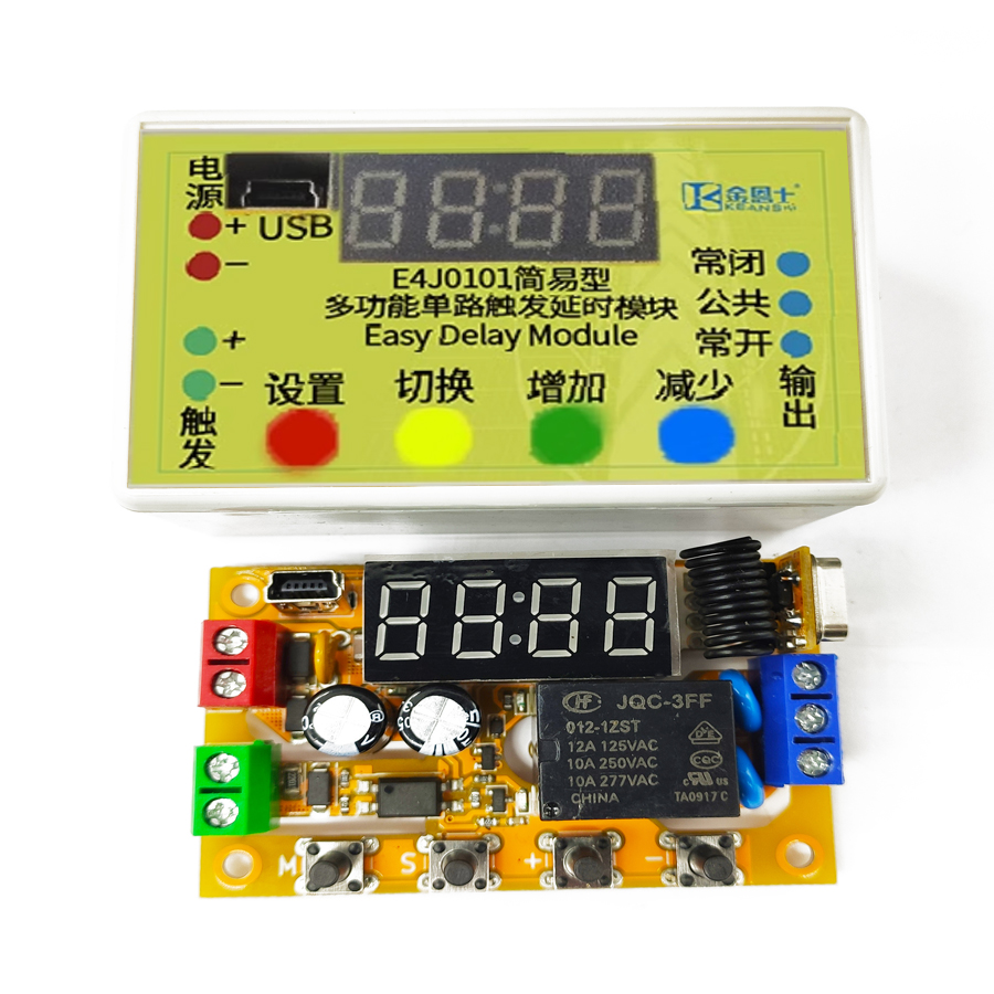
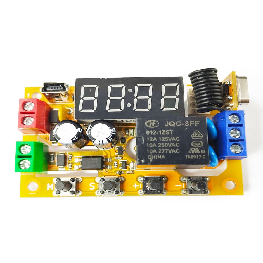
The E4J0101 is a multi-functional single-channel digital delay module built around a dedicated integrated circuit. It has one trigger signal input and one relay output, with an on-board digital tube and configuration keys. Depending on the model, the trigger input can be analog or optocoupler-isolated digital, and the output can be a relay or a transistor. Some models include wireless remote triggering. All models offer USB and TTL serial connectivity for PC-based configuration and firmware upgrades — upgrade the firmware to unlock new functions.
Note: the configuration software is packed with shell-protection technology. Some popular anti-virus tools may flag it as a false positive — please add it to your trust list.
Product Features
High Flexibility
- One optocoupler high-voltage isolated digital trigger input.
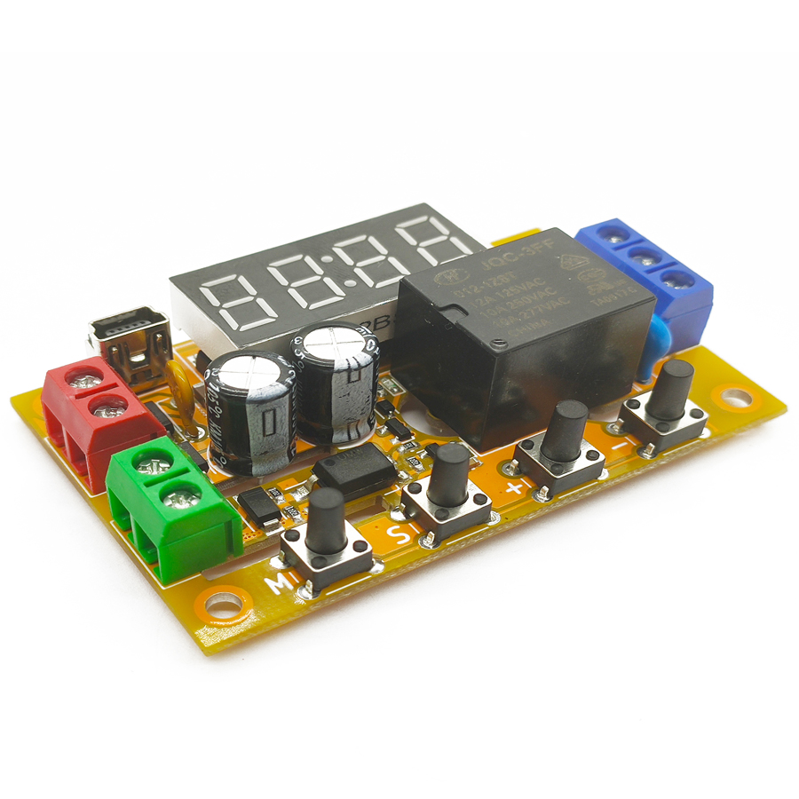
- One arc-suppression relay or transistor digital output.
- Up to 100 independent delay modes.
High Usability
- Built-in digital tube and keys for on-site function setting.
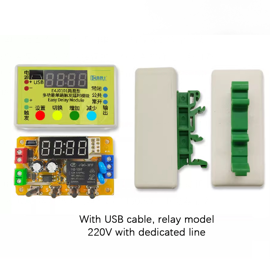
- Configurable via USB connection to a computer.
High Expandability
- Controllable via USB interface.
- Expandable with one TTL serial port, controllable via serial commands.
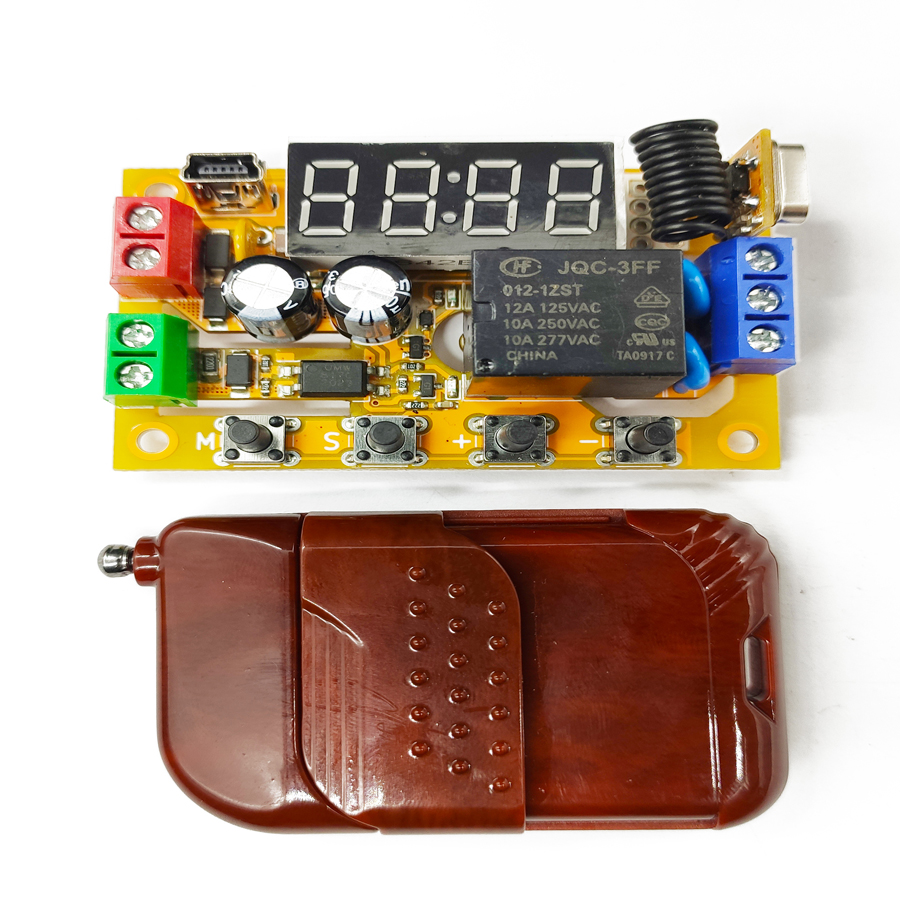
- Optional remote-control function — trigger the module with a wireless remote.
- Firmware upgradeable to obtain new extended functions.
High Reliability
- Measured 1500 V DC optocoupler input isolation.
- Industrial-grade 2000 V EFT and 4000 V ESD tolerance.
- Reverse-polarity, overcurrent and surge protection for the power supply.
- High-voltage-side PCB creepage distance compliant with safety regulations.
Introduction
This product is a multifunctional single-channel digital delay module with a dedicated integrated circuit as its core. It features one trigger signal input and one output, and is equipped with a digital tube and buttons for on-site configuration. Depending on the model, its output can be either a relay or a transistor. Some models also have wireless capabilities, allowing remote triggering via a remote control. All models come with USB connection and serial-port functions for PC-based settings and firmware updates — upgrading firmware unlocks new functions. Out of the factory, the default delay accuracy is 1.5 % across the full temperature range; after upper-computer calibration, accuracy can be tightened to within 0.1 %.
Configuration Instructions
After powering on the product, hold down the “M” button for a long time to unlock the settings. The product enters configuration mode and the digital tube displays the menu. Press “−” or “+” to navigate menus. Briefly press “M” to enter or exit a menu. When the adjustment is complete, hold the “M” button again to exit configuration and save the settings. In configuration mode, any ongoing delay sequence stops immediately and no new triggers are accepted. After entering a menu, the item being adjusted flashes slowly; press “S” to select an item, “+” to increase it, and “−” to decrease it. The adjustable range varies per menu.
Delay Mode Description
The module ships with approximately 100 basic delay templates. Combined with input/output polarities, they form roughly 1,000 specific delay modes. The basic templates fall into five groups: Switch Function, Delayed Disconnection, Delayed On-Off, Cyclic Delay, and Counting Delay.
Both the input and the output of each delay group can be inverted. If the input is inverted, a valid trigger signal is treated as invalid and vice-versa; if the output is inverted, “connected” becomes “disconnected”. Each specific delay mode therefore has four derivative modes: both normal, input inverted, output inverted, and both inverted. Additionally, every mode that accepts trigger input can optionally be triggered once on power-up, and the output state before the first trigger can be specified.
Delay Mode Groups
| Group | Group Number | Group Content |
|---|---|---|
| Switch Function | 0 | Simple switch function. Includes "Point Operation" and "Self-Locking". |
| Delayed Disconnection | 1 | When power is applied or a trigger signal arrives, the output is connected and disconnected after a delay. Includes "Signal-Triggered Connection with Delayed Disconnection" and "Signal-Triggered Connection, Disconnected after Signal Removal with Delay". |
| Delayed On-Off | 2 | When power is applied or a trigger signal arrives, the output is disconnected and the first delay starts. After the first delay ends, the output is connected and the second delay begins. After the second delay ends, the output is disconnected again. Includes "Signal-Triggered with Delayed Connection" and "Signal-Triggered with Delayed Connection and Delayed Disconnection". |
| Cyclic Delay | 3 | When power is applied or a trigger signal arrives, the output is repeatedly connected and disconnected according to a certain pattern for a certain number of times. Includes "Signal-Triggered with Repeated Connection for a Certain Time and Disconnection for a Certain Time, Cycled a Certain Number of Times". |
| Counting Delay | 4 | The output is connected after the trigger signal arrives a certain number of times. Includes "Connected after the Signal Arrives a Certain Number of Times with Delayed Disconnection". |
Delay Mode Selection Guide
Pick a suitable delay mode using the strategy below. When a step asks about input or output status, it refers to the status after all preceding steps have been processed — this unifies complex delay functions into standard modes through a standardized input/output method for easy table lookup. For example, if the original delay scheme is “falling-edge triggered” at step 1, invert the input — the inverted input becomes “rising-edge triggered”, which is what you look up at step 6. Likewise, a “disconnected first, then connected permanently after a delay” output at step 3 becomes “connected first, then disconnected permanently after a delay” once inverted.
Throughout the templates, “high level” indicates the signal is valid, “low level” means invalid; “rising edge” is low → high, “falling edge” is high → low.
Counting Delay (8)
The counting-delay group contains modes that cannot be achieved by other modes combined with a non-zero loop count L, so they form a separate category. Within these modes, setting the loop count L = 0 means the output is either never triggered regardless of the number of rising edges, or there is no limit on the number of triggerable times.
Remote-Control Function
The remote-control function is only available on the remote-control model. After power-on, press and hold the “S” key — the digital tube shows a flashing wave, indicating code-pairing mode. Hold down the supplied remote until the digital tube goes out; the module now remembers this remote and automatically exits code pairing. For multi-key remotes, only one key is paired — the others are inactive, allowing different keys to address different modules. To disable the remote function, press and hold “S” in pairing mode again to exit directly.
Each key press is treated as a single effective trigger pulse of ~500 ms (rising edge → high level → falling edge). Keys are auto- debounced; holding a key acts as a continuous high level until released for more than 500 ms. The input-polarity setting has no effect on the remote control.
TTL Serial Port & AT Protocol
The AT protocol is an ASCII command set with a series of short instructions that perform simple operations on the module's input and output. AT commands start with AT and end with \r\n (<CR><LF>, 0x0D 0x0A); on this product the ending is optional. AT commands are usable out-of-the-box; TTL serial parameters are fixed at 1500 baud, no parity, 1 stop bit. Send a bare AT to test the link — the module replies with OK if the serial port is working. There is no echo; ATE0 echo control is not supported. Send one complete AT command per transmission.
Frequently Asked Questions
How accurate is the E4J0101 delay timing?
Out of the factory the delay accuracy is 1.5 % across the full temperature range. After calibration with the upper-computer (PC) software over USB, accuracy can be tightened to within 0.1 %. This makes the E4J0101 suitable for timing-critical DIN-rail delay applications where a generic timer relay would drift.
How is the E4J0101 different from a safety relay?
The E4J0101 is a configurable delay/timer relay module, not a safety relay with forcibly-guided contacts and EDM feedback. It handles flexible delay, cyclic and counting logic for general automation sequencing. For emergency-stop or light-curtain stop circuits you need a dedicated safety relay or safety PLC instead; the two are complementary, not interchangeable.
How do I configure the E4J0101 without a computer?
Every model has an on-board digital tube and keys. Power on, then hold the "M" button to unlock settings and enter configuration mode. Use "−" and "+" to navigate, "M" to enter or exit a menu, and "S" to select an item. Hold "M" again to save and exit. No PC, USB or TTL serial connection is required for basic setup.
Can I control the E4J0101 over a serial port or wirelessly?
Yes. All models expose a USB port and a TTL serial port fixed at 1500 baud, no parity, 1 stop bit, using a simple ASCII AT command protocol — send a bare AT and the module replies OK. Remote-control models also pair to a wireless remote: each key press acts as a ~500 ms trigger pulse, so different keys can address different modules.
How well is the E4J0101 protected against electrical noise?
The digital trigger input is optocoupler-isolated with a measured 1500 V DC isolation. The module withstands industrial-grade 2000 V EFT bursts and 4000 V ESD, and the power input has reverse-polarity, overcurrent and surge protection. High-voltage-side PCB creepage distances follow safety regulations, so it tolerates noisy DIN-rail panels.
Specs reviewed by Engineer Cai, Senior Application Engineer. See certificates.
Safety Light Curtain — Customer Cases
Real installations from DAIDISIKE clients. Click any case to view in full. Filter by scenario to quickly find a similar setup.