
E4J0102 Clock-Measuring Pressure Delay Module
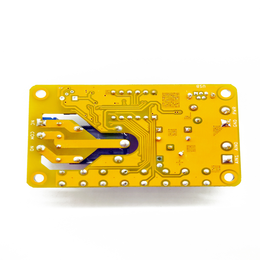
The E4J0102 is a multi-functional single-channel digital delay module built around a dedicated integrated circuit. It has one trigger signal input and one relay output, with an on-board digital tube and configuration keys. Depending on the model, the trigger input can be analog or optocoupler-isolated digital, and the output can be a relay or a transistor. Selected models include a real-time clock for triggering at a fixed time of day, and some support wireless remote triggering. All models offer USB and TTL serial connectivity for PC-based configuration and firmware upgrades.
Note: the configuration software is packed with shell-protection technology. Some popular anti-virus tools may flag it as a false positive — please add it to your trust list.
Product Features
High Flexibility
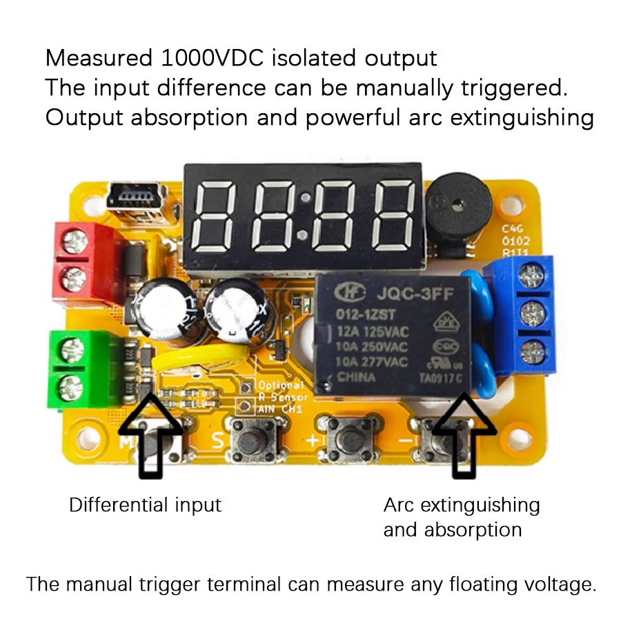
- One non-isolated differential external analog voltage detection channel.
- Analog voltage detection operates in hysteresis mode or range mode.
- One arc-suppression relay or transistor digital output.
- Up to 100 independent delay modes.
High Usability
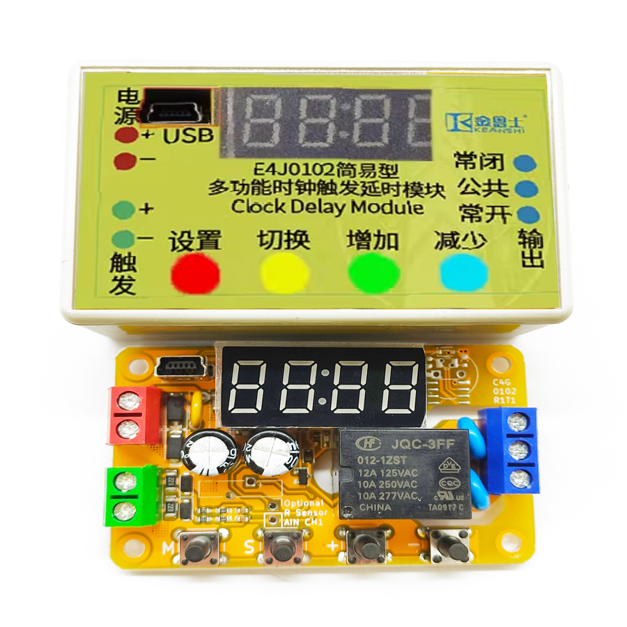
- Built-in digital tube and keys for on-site function setting.
- Configurable via USB connection to a computer.
High Expandability
- Controllable via the USB interface.
- Expandable real-time clock function — triggers the module at a fixed time point.
- Firmware upgradeable to obtain new extended functions.
High Reliability
- Industrial-grade 2000 V EFT and 4000 V ESD tolerance.
- Reverse-power, overcurrent and surge protection.
- High-voltage-side PCB creepage distance compliant with safety regulations.
Introduction
This product is a multifunctional single-channel digital delay module with a dedicated integrated circuit at its core. It features one trigger signal input and one relay output, equipped with a digital tube and buttons for on-site configuration. Depending on the model, its trigger input can accept either analog or digital signals, and its output can be either a relay or a transistor. Some models also have a real-time clock function, allowing the module to trigger at a fixed time point.
All models are equipped with USB and serial-port functions, enabling connection to a computer for settings or firmware updates. Upgrading the module to the latest firmware unlocks new functions.
After powering on this product, hold down the “M” button to unlock the settings — the product enters configuration mode and the digital tube displays the menu. Press “−” or “+” to navigate menus, and briefly press “M” to enter or exit a menu. When adjustment is complete, hold the “M” key again to exit configuration and save the product settings. In configuration mode, any ongoing delay sequence stops immediately and no new triggers are accepted. After entering a menu, the item being adjusted flashes slowly: press “S” to select the item, “+” to increase, and “−”to decrease. There are up to ten menus on this product; modified versions without a real-time clock have only the first seven available, and versions without a buzzer disable the buzzer-related functions.
Delay Mode Description
The module is equipped with approximately 100 basic delay templates. Combined with input / output polarities, they form roughly 1,000 specific delay modes. The basic templates fall into five groups: Switch Function, Delay Off, Delay On / Off, Cyclic Delay, and Counting Delay.
Both the input and the output of each delay group can be inverted. If the input is inverted, a valid trigger is treated as invalid and vice-versa; if the output is inverted, “connected” becomes “disconnected”. Each specific delay mode therefore has four derivative modes: both normal, input inverted, output inverted, and both inverted. Additionally, every mode that accepts trigger input can optionally be triggered once on power-on, with the pre-trigger output state user-specifiable.
Delay Mode Groups
| Group | Group Number | Group Content |
|---|---|---|
| Switch Function | 0 | Simple switch function — “Point-to-point” and “Self-locking”. |
| Delayed Disconnection | 1 | When power is applied or a trigger arrives, the output connects and then disconnects after a delay. Includes “Signal-triggered connection with delayed disconnection” and “Signal-triggered connection, delayed disconnection after signal removal”. |
| Delayed On-Off | 2 | When power is applied or a trigger arrives, the output disconnects and the first delay starts. After the first delay, the output connects and the second delay begins. After the second delay, the output disconnects again. |
| Cyclic Delay | 3 | After power-up or trigger, the output is repeatedly connected and disconnected per a pattern for a certain number of times. |
| Counting Delay | 4 | The output connects after the trigger signal arrives a certain number of times — “Connected and delayed disconnection after the signal arrives more than a certain number of times”. |
Delay Mode Selection Guide
Select a suitable delay mode by following the steps below. When a step asks about input or output status, it refers to the status after all preceding steps have been processed — this unifies complex delay functions into standard templates through a standardized input / output method for easy table lookup. For example, “falling-edge triggered” at step 1 becomes “rising-edge triggered” after inverting the input — that is what you look up at step 6.
| Step | Question | Answer |
|---|---|---|
| 0 | Is the output function only a simple switch? | Yes: look up the “Switch Function” group and go to step 8. No: go to step 1. |
| 1 | Is there a signal or rising-edge trigger? | Yes: go to step 2. No: invert the input and go to step 2. |
| 2 | Is the output connected when powered on? | Yes: set the output to be connected on power-on and proceed to step 3. No: proceed to step 3. |
| 3 | Does the output eventually disconnect after the delay? | Yes: proceed to step 4. No: invert the output and proceed to step 4. |
| 4 | Is there a repeated on-off cycle during the delay? | Yes: search the “Cyclic Delay” group and proceed to step 7. No: proceed to step 5. |
| 5 | Is there a count for the trigger input signal? | Yes: search the “Counting Delay” group and proceed to step 7. No: proceed to step 6. |
| 6 | Does the output connect immediately after triggering? | Yes: search the “Delayed Disconnect” group and proceed to step 7. No: search the “Delayed On-Off” group and proceed to step 7. |
| 7 | Has the required delay template been found? | Yes: proceed to step 8. No: please apply for a custom delay mode. |
| 8 | Is an additional trigger required on power-on? | Yes: set the input to trigger once on power-on and proceed to step 9. No: proceed to step 9. |
| 9 | Is the total number of actions since power-on limited, or has the “Cyclic Delay” group been selected? | Yes: set the cycle count L to the maximum number of actions or cycles. No: set the cycle count L to 0. |
Throughout the templates, “high level” indicates the signal is valid, “low level” means invalid; “rising edge” is low → high, “falling edge” is high → low.
Delayed On-Off (34)
The delayed on-off group includes 34 modes. “Invalid” means it does not affect the delayed action; “Stop” means it returns to the untriggered state. Setting the loop count L to any non-zero value allows at most L complete delays since power-on; once L delays are reached, the module cannot be triggered again.
Cyclic Delay (18)
The cyclic delay group includes 18 modes. Where the number of cycles is limited, the last cycle also includes delay C. Setting the cycle count L to 0 means an infinite loop.
Counting Delay (8)
The counting-delay group contains modes that cannot be achieved by other modes combined with a non-zero loop count L, so they form a separate category. Setting L = 0 means the output is either never triggered regardless of the number of rising edges, or there is no limit on the number of triggerable times.
Setting Delay Times A and C
To set delay times A and C, enter the P--A and P--C menus respectively. The two menus have a similar structure. If a delay time is set to 0, it is treated as 10 milliseconds.
Trigger Threshold Description
The product has a non-isolated analog voltage detection terminal that is non-polarized — it can be connected with either positive or negative polarity. The voltage of either detection terminal to the power-supply negative terminal must not be lower than 0 V or higher than 30 V. The absolute value of the voltage difference between the two detection terminals is the trigger voltage.
When the High Trigger Threshold ≥ Low Trigger Threshold, the analog detection terminal operates in hysteresis mode: input above the high threshold is “high level”; below the low threshold is “low level”; between the two it holds the previous level. This prevents repeated triggering and false triggering.
When the High Trigger Threshold < Low Trigger Threshold, the terminal operates in range mode: input within the range counts as “high level”; outside the range it is “low level”. This supports voltage-clamping or out-of-range alarm applications.
After the analog voltage is converted to a digital level using the rules above, the digital level is preprocessed according to the “Input Mode” before triggering — if the input is set to invert, the digital level is inverted.
Firmware Upgrade via USB
The product supports firmware upgrades through dedicated software. New firmware may include functional updates, bug fixes and reliability enhancements without changing the validity of existing functions. Firmware is packaged with the dedicated software — each software version corresponds to a new firmware. To upgrade: connect the product to a PC via USB, click “Firmware Upgrade”, and wait a short time. Do not power off or unplug the USB cable during the upgrade.
In addition to standard firmware, you can upgrade to quick-adjust firmware for situations where it is important to conveniently adjust delay parameters. The quick-adjust firmware does not let you adjust input / output polarity, delay mode or the real-time clock from the digital tube and buttons — only delay times A & C and the loop count L. Switch back by upgrading to the standard firmware again. Under quick-adjust firmware, long-press S to enter delay-A adjustment, long-press + to enter delay-C adjustment, and long-press − to enter loop-count L adjustment. Short-press + / − changes the value by 1; long-press adjusts by 50 for delays A/C, or by 100 for loop count L. Press M to exit and save.
Input / Output Read / Write
The “input / output read / write” area manually controls relay connection / disconnection, detects the input level, and triggers the delay manually. Communication parameters are determined by the serial-port number. In some delay modes the priority of the selected mode is higher than manual control — writing to the output may not take effect (e.g. mode 0000, point mode). This is normal.
Remote-Control Function
Only available on the remote-control model. After power-on, press and hold the “S” key — the digital tube shows a flashing wave, indicating code-pairing mode. Hold down the supplied remote until the digital tube goes out; the module now remembers this remote and auto-exits pairing. For multi-key remotes, only one key is paired — the others are inactive, allowing different keys to address different modules. To disable, press and hold “S” again in pairing mode to exit. Each key press is treated as a single 500 ms trigger pulse (rising edge → high level → falling edge); auto-debounce is included; holding a key acts as a continuous high level until released for > 500 ms. The input polarity setting has no effect on the remote control.
TTL Serial Port & AT Protocol
The AT protocol is an ASCII command set with short instructions that perform simple operations on the module's input and output. AT commands start with AT and end with \r\n (<CR><LF>, 0x0D 0x0A); on this product the ending is optional. AT commands are usable out-of-the-box; TTL serial parameters are fixed at 1500 baud, no parity, 1 stop bit. Send a bare AT to test the link — the module replies OK if the serial port is working. There is no echo; ATE0 echo control is not supported. Send one complete AT command per transmission.
Frequently Asked Questions
What is the E4J0102 clock-measuring pressure delay module used for?
It is a multi-functional single-channel digital delay relay module that triggers a relay or transistor output based on an external analog voltage. With around 100 delay templates plus input/output inversion (about 1,000 specific modes) it covers delay-off, delay on/off, cyclic and counting delays — ideal for press, timing and pressure-threshold automation where a programmable DIN-rail delay relay is needed.
How does the analog voltage trigger work in hysteresis vs range mode?
The non-isolated differential detection terminal reads the voltage difference between its two inputs (0–30 V each to supply negative). When the high threshold is greater than or equal to the low threshold it runs in hysteresis mode to block chatter and false triggering. When the high threshold is below the low threshold it runs in range mode, so an in-range voltage is 'high' — useful for voltage-clamping or out-of-range alarm jobs.
Does the E4J0102 have a real-time clock for time-of-day triggering?
Selected models include an expandable real-time clock that triggers the module at a fixed time point, so you can schedule outputs by time of day rather than only by signal edge. Modified versions without the clock expose only the first seven of the ten on-board menus. The clock works alongside the analog trigger and the 100 delay templates.
How do I configure it — USB software or on-board keys?
Both. The module has an on-board digital tube and M/S/+/− keys for on-site setup, and a USB plus TTL serial interface for PC configuration and firmware upgrades. TTL serial is fixed at 1500 baud, no parity, 1 stop bit, and supports an AT command set. Note the configuration software uses shell protection and may be flagged by anti-virus as a false positive.
Is a safety relay or a safety PLC better than this delay module?
The E4J0102 is a functional timing/delay relay, not a safety-rated device. For emergency-stop, light-curtain or guard-door circuits you need a safety relay with forcibly guided contacts and EDM feedback, or a safety PLC. Use the E4J0102 for sequencing, delays and analog-voltage thresholds; it offers industrial-grade 2000 V EFT / 4000 V ESD tolerance and reverse-power, overcurrent and surge protection.
Specs reviewed by Engineer Cai, Senior Application Engineer. See certificates.
Safety Light Curtain — Customer Cases
Real installations from DAIDISIKE clients. Click any case to view in full. Filter by scenario to quickly find a similar setup.