This product is a power-on delay module. It can be used with voltages of 5V, 9V, 12V, 18V or 24V. After the circuit is powered on, it will close after a delay. This delay time can be adjusted by a potentiometer. This circuit has no trigger input terminal, and the delay time is calculated from the moment of power-on.
This product is a power-up delay module that can be powered from 5V, 9V, 12V, 18V or 24V. After the product is powered up, the relay will make after a variable delay that can be adjusted through the on-board potentiometer. No trigger input is provided and the countdown starts right after the product is powered up.
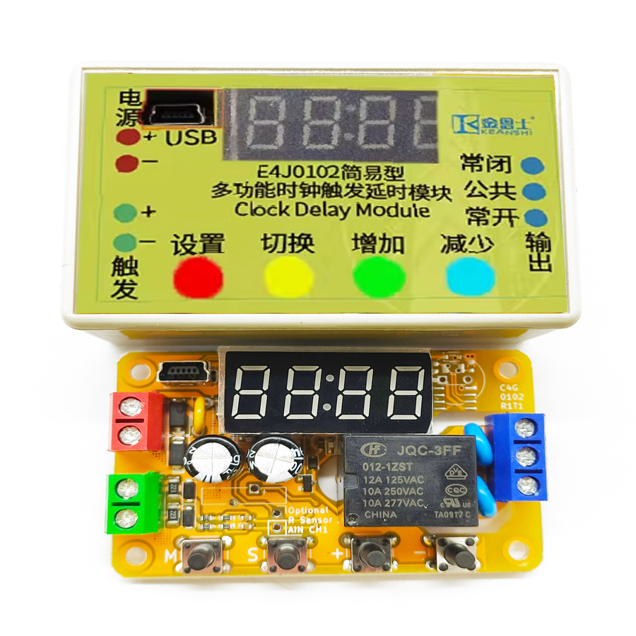
1.2 Structural Description
There are five screw terminals, one button, one potentiometer and two LED indicators on the product. The description of each terminal and component is shown in the figure and table below.
Table 1-1 Product Front-side Marking
Name
No.
Meaning
Normally open contact
0
The Normally Open (NO) contact of the relay. When the relay makes, this is connected to the common contact. Blue. For transistor output type, this serves as the load ground.
Common contact
1
The COMmon (COM) contact of the relay. Blue. For transistor output type products, this serves as the load-side power supply ground.
Normally closed contact
2
The Normally Closed (NC) contact of the relay, when the relay breaks, this is connected to the common contact. Blue. For transistor output type, this serves as the common terminal of load and load-side supply.
Negative supply
3
Negative power supply. The typical current consumption when the relay makes is 40 mA. Red.
Positive supply
4
Positive power supply. The typical current consumption when the relay makes is 40 mA. Red.
Adjusting knob
5
The knob for adjusting the delay time. Blue.
Action indicator
6
The indicator for the relay status. Blue.
Power indicator
7
The indicator for the power status. Green.
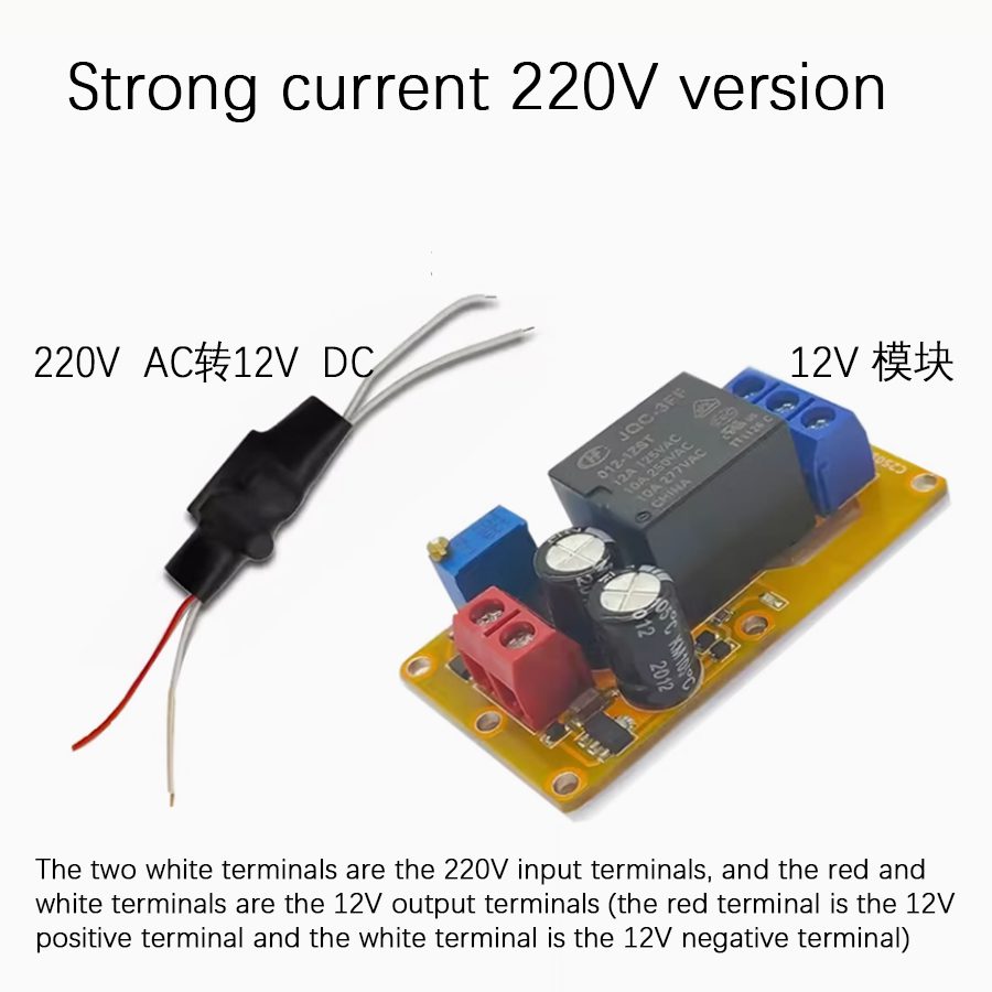
1.3 Wiring Methods
When the product lacks a case, it is only recommended for controlling the safe voltage (0-36V) rather than the AC mains. Special care should be taken to prevent electric shock when a caseless product is used to control the AC mains. Please be gentle when tightening the screws to avoid stressing the product PCB. Long-term reliability of the product may be affected when the screw is too overtightened.
Frequently Asked Questions
What does a power-on delay relay module do?
It delays closing the relay for a set interval after the circuit is powered up. The B2J0101 has no external trigger input — the countdown begins the moment power is applied, and the relay makes (closes) once the delay elapses. This is useful for sequencing equipment start-up, suppressing inrush, or staggering loads in industrial automation timing applications.
What supply voltages does the B2J0101 support?
The B2J0101 runs from 5V, 9V, 12V, 18V or 24V DC, so one DIN-rail delay relay module covers most low-voltage control circuits. Typical current consumption is about 40 mA when the relay is energized. Connect the positive supply to terminal 4 and the negative supply to terminal 3.
How do I adjust the delay time?
Turn the on-board potentiometer (adjusting knob, terminal mark 5). There is no trigger terminal, so the adjustable delay is measured from power-on to relay closure. The action indicator (mark 6) shows relay status and the green power indicator (mark 7) confirms supply, making it easy to verify timing during setup.
Can it switch AC mains voltage?
When supplied without a case, the B2J0101 is recommended only for safe extra-low voltage control (0–36 V), not AC mains. If a caseless board is used near AC mains, take special care to prevent electric shock. It offers normally open (NO), common (COM) and normally closed (NC) contacts, plus a transistor output variant.
Is this a safety relay, and how should I wire it?
No — the B2J0101 is a general-purpose timing/delay relay, not a forcibly-guided safety relay for emergency-stop circuits. For safety functions use a dedicated safety relay or safety PLC with EDM. Wire NO to terminal 0, COM to terminal 1, NC to terminal 2; tighten screws gently to avoid stressing the PCB and harming long-term reliability.