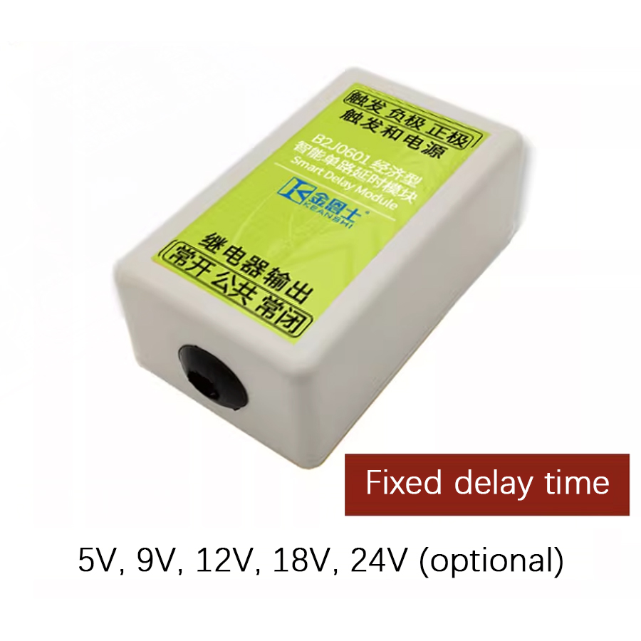
This is an intelligent delay module with a dedicated smart delay integrated circuit at its core. It can be used in conjunction with 5V, 9V, 12V, 18V or 24V voltages. This module supports three delay units and eight basic delay templates, combining into 26 delay modes, which basically cover all common scenarios. The delay mode and delay unit can be conveniently adjusted through a single button. Compared with competing products, one of the prominent features of this product is its high delay accuracy, with long-term delay accuracy up to 30ppm. The input terminal of this product can also perform additional voltage detection functions, further increasing the flexibility of its application.
This product is an intelligent delay module implemented with smart ASIC technology. It may be powered from 5V, 9V, 12V, 18V, or 24V. This product supports 26 delay modes, which basically cover all common occasions. The delay mode and unit may be easily adjusted through a button. The high delay accuracy of the product is one of the outstanding features compared to competing products, and its long delay accuracy may be as high as 30 ppm. The additional voltage detection function may be performed on the input terminal of the product, which makes it even more flexible. The functionality of the product is completely customizable per request in mass production.
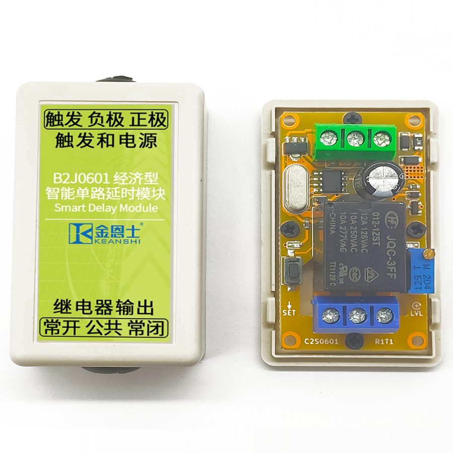
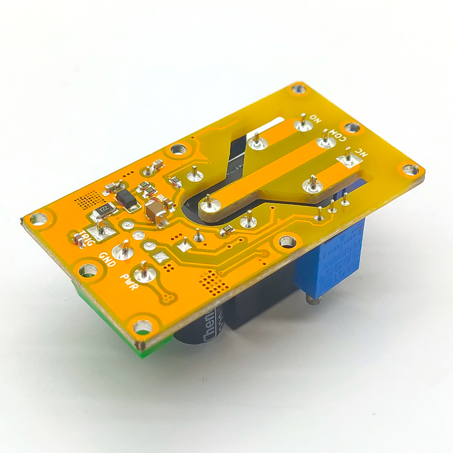
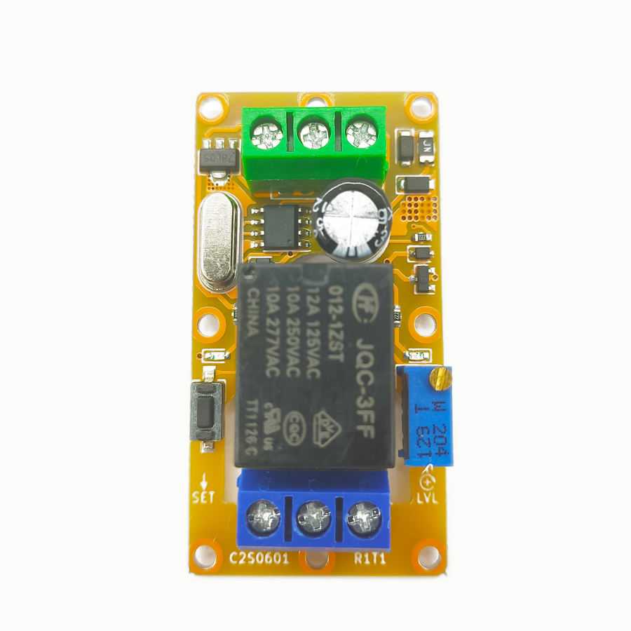
Structural Description
There are six screw terminals, one button, one potentiometer, one jumper, and two LED indicators on the product. The description of each terminal and component is shown in the figure and table below.
Chapter 2: Detailed Function Description
2.1 Configuration Unlocking Description
To adjust the delay mode and time, unlocking the settings is needed first. To unlock the settings, keep the button pressed, then connect the power supply to the module. After about 3 seconds, the relay on the product will make, and the indicator light will turn on, indicating that the unlocking is complete. At this point, release the button and keep the product powered on to unlock the product's delay mode and time settings for this power cycle only. Then, both the delay time and mode may be configured as described in the following sections. After the configuration is complete, release the button and power cycle the product. The product will not respond to key presses unless the settings are unlocked, ensuring that the delay mode and time will not be unintentionally tampered with during normal operation.
2.2 Configuration Reset Description
To reset the delay mode and time to factory defaults, press and hold the button, then connect the power supply to the module. After about 3 seconds, the product will be unlocked; keep holding the button for more than 10 seconds until the product's relay and indicator alternate rapidly on and off, indicating that the configuration reset is complete. After the configuration reset is complete, the new delay mode and time may be set directly without power cycling again, as the configuration has been unlocked.
2.3 Delay Mode Description
This product has 3 delay time units and 8 basic delay templates built-in, which are combined to form 24 delay modes, plus two self-locking modes, for a total of 26 delay modes. A short press of the button will cycle through all 26 delay modes of the product. For each short press, the delay mode will switch to the next one in the table, while the indicator light will flash according to certain patterns to indicate the currently selected delay mode. The specific pattern is that the indicator first flashes 1–4 times at an interval of 0.5 seconds to represent the delay time unit, and then flashes 1–8 times at an interval of 0.5 seconds after a pause of 1.5 seconds to indicate the basic delay template.
Since the indicator is connected to the relay, the relay will also toggle when the delay mode is adjusted. Therefore, when adjusting the delay mode, it is recommended to disconnect all electrical connections on the relay unless it is confirmed that the toggling of the relay will not affect the load. The specific 26 delay modes are listed in the table below.
Table 2-1: List of Delay Modes
No.
Delay Unit
Delay Action
Indicator Light Flashes
11
Second
High-level triggers, breaks after a delay period
Flashes once, then flashes again after a short pause
12
Second
Low-level triggers, breaks after a delay period
Flashes once, then flashes twice after a short pause
13
Second
Rising edge triggers, breaks after a delay period
Flashes once, then flashes 3 times after a short pause
14
Second
Falling edge triggers, breaks after a delay period
Flashes once, then flashes 4 times after a short pause
15
Second
High-level sustains, on-off-on toggling with delay intervals
Flashes once, then flashes 5 times after a short pause
16
Second
Low-level sustains, on-off-on toggling with delay intervals
Flashes once, then flashes 6 times after a short pause
17
Second
Rising edge triggers, on-off-on toggling with delay intervals
Flashes once, then flashes 7 times after a short pause
18
Second
Falling edge triggers, on-off-on toggling with delay intervals
Flashes once, then flashes 8 times after a short pause
21
Minute
High-level triggers, breaks after a delay period
Flashes twice first, then flashes once after a short pause
22
Minute
Low-level triggers, breaks after a delay period
Flashes twice first, then flashes twice after a short pause
23
Minute
Rising edge triggers, breaks after a delay period
Flashes twice first, then flashes 3 times after a short pause
24
Minute
Falling edge triggers, breaks after a delay period
Flashes twice first, then flashes 4 times after a short pause
25
Minute
High-level sustains, on-off-on toggling with delay intervals
Flashes twice first, then flashes 5 times after a short pause
26
Minute
Low-level sustains, on-off-on toggling with delay intervals
Flashes twice first, then flashes 6 times after a short pause
27
Minute
Rising edge triggers, on-off-on toggling with delay intervals
Flashes twice first, then flashes 7 times after a short pause
28
Minute
Falling edge triggers, on-off-on toggling with delay intervals
Flashes twice first, then flashes 8 times after a short pause
31
Hour
High-level triggers, breaks after a delay period
Flashes 3 times first, then flashes once after a short pause
32
Hour
Low-level triggers, breaks after a delay period
Flashes 3 times first, then flashes twice after a short pause
33
Hour
Rising edge triggers, breaks after a delay period
Flashes 3 times first, then flashes 3 times after a short pause
34
Hour
Falling edge triggers, breaks after a delay period
Flashes 3 times first, then flashes 4 times after a short pause
35
Hour
High-level sustains, on-off-on toggling with delay intervals
Flashes 3 times first, then flashes 5 times after a short pause
36
Hour
Low-level sustains, on-off-on toggling with delay intervals
Flashes 3 times first, then flashes 6 times after a short pause
37
Hour
Rising edge triggers, on-off-on toggling with delay intervals
Flashes 3 times first, then flashes 7 times after a short pause
38
Hour
Falling edge triggers, on-off-on toggling with delay intervals
Flashes 3 times first, then flashes 8 times after a short pause
43
Self-locking
Rising edge triggers, toggles on and off on each trigger in a self-locking manner
Flashes 4 times first, then flashes 3 times after a short pause
44
Self-locking
Falling edge triggers, toggles on and off on each trigger in a self-locking manner
Flashes 4 times first, then flashes 4 times after a short pause
When retail version products are shipped, the selected delay mode is always 11. The full-featured retail version has all 26 delay modes; the simplified retail version has 12 delay modes in total, including 11, 12, 13, 14, 21, 22, 23, 24, 31, 32, 33, and 34.
2.4 Delay Time Description
The delay time of this product is also adjusted by the same button. To adjust the delay time, press and hold the button until the indicator starts to flash. Each complete blink of the indicator light represents one unit of delay time. Incomplete blinks will not be counted. The range of delay time setting is 0–255. When the delay time is set to 0, in the high-level or low-level triggering templates, the only function that remains is voltage detection and thresholding. The delay capability is lost, and the rising edge and falling edge trigger templates are invalid. If the delay time is set to 0 when one of the on-off-on toggling templates is chosen, the delay time will be regarded as 500 ms.
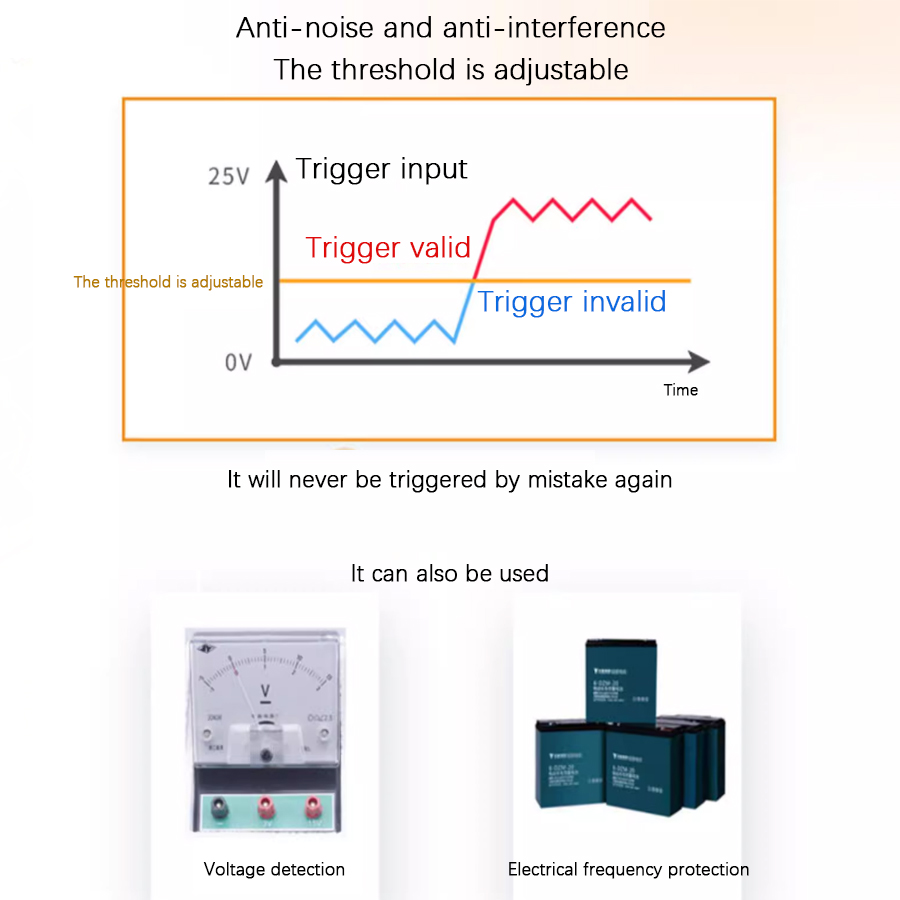
2.5 High-Level Thresholding Description
The trigger terminal of this product may accept an input voltage from 0–30V. The voltage threshold decides whether a particular input voltage is high level or low level. A voltage above the threshold is considered high-level, and a voltage below the threshold is considered low-level. This threshold is adjusted through a knob. Rotating it clockwise will set the threshold higher, and vice versa. The trigger terminal of this product may withstand up to 50V over a long period, but it may be damaged if this is exceeded. Any voltage exceeding 35V is treated as high-level regardless of the knob setting.
2.6 Mass Customization Description
The core of this product is a dedicated intelligent delay integrated circuit, so its delay time, mode, and voltage threshold may be arbitrarily customized. When customizing, all delay or action sequences different from the factory standard ones may be used. All parameters may be preconfigured to any value at the factory, and the wiring terminals, buttons, indicators, and potentiometers may be omitted to lower costs. You may also return a preconfigured retail-version product that has been fully set up and ask us to produce a version with the exact same presets, which helps reduce the tedious process of confirming the demand details.
Chapter 3: Product Modifications
3.1 Preface
This product has the following modifications whose ordering numbers are in the form of B2J06[aa]R[b]T[c]M[dd]. The [aa] field is fixed as 01, as the module only has a single-channel version; the [b] field and [c] field are the main version number and sub-version number of the module, respectively; the [dd] field determines the specific modification of the module. The module modification classes are mutually independent. If no specific requirement is designated when the product is shipped, the default option is the 12V relay output type, that is, M31.
3.2 Transistor Output Type Description
This version is connected to the circuit in open-drain mode. The transistor has a rated working voltage of 12–48V DC and a rated current of 10A. With a 10A freewheeling diode on the transistor, it can directly power an inductive load up to 10A. Certain loads, e.g., filament lamps, mercury lamps, exhibit a current spike during startup; some other loads, e.g., heavy-duty motors, speakers, and electromagnets, emit extremely strong EMI during operation. Due to size limitations, it is impossible to implement good power line filters on this module; thus, when the power of such loads exceeds 1W, it is recommended to use standalone power sources for the module and to place these loads as far as possible from the module, or the module may repeatedly reset when the load powers on.
Compared to relays, transistors are far more sensitive. Thus, when the module is being powered on or off, the internal states of the microcomputer may become invalid; even if the delay is untriggered, the transistor may make for a moment and then break. This issue is nonexistent in the relay version but must be accounted for when using transistor version modules, especially when the devices connected to the output may respond to such momentary pulses. An effective countermeasure is to use power sequencing: ensure that the product is powered on before the output is powered on and that the output is powered off before the product is powered off.
Relay type: DC 30V or AC 0–220V, 8A Transistor type: DC 12–48V, 8A
Output isolating voltage
Relay type: Less than 250V Transistor type: Less than 130V
Operating temperature
-20–60℃
4.2 Absolute Maximum Ratings
The extreme conditions that this module can withstand are shown in the following table. Stresses at or above those listed here may permanently damage the module.
Description
Range
Supply voltage
5V DC: 5.3V 9V DC: 11.5V 12V DC: 15V 24V DC: 30V
Self-resettable fuse
DC 30V, 500mA
Input stress
DC 50V
Output stress
Relay type: AC 250V, 10A Transistor type: DC 55V, 10A
Output isolating voltage
Relay type: DC 1000V, 60s (Type test only) Transistor type: DC 250V, 60s (Type test only)
Relay mechanical life
Relay type: More than 100,000 times (Actual life varies with load, >10,000 times under heavy load)
Storage temperature
-40–85℃
4.3 Other Parameters and Certifications
The other parameters and certifications of this module are listed as follows. These parameters and certifications include electrostatic discharge, electrical fast transient, and voltage surge tests that comply with the requirements of IEC61000-6-1-2016 (Edition 3.0, 2016-08) for light industry purposes. During all of these tests, the modules are powered by a well-grounded 12V supply and in active delay operation.
4.4 Notes on Reliability
This product is only qualified for commercial applications due to its miniature size; thus, it is not recommended for formal industry situations with strong interference. Additional power filters and/or port filters are required if it must be used in this way. If such additional filters are not desired, a switching power supply with Electrical Fast Transient (EFT) resistance is required to power the product, and the power supply cord must be shorter than 3m.
In addition, if the load exhibits current spikes during startup or emits extremely strong EMI during operation, it is recommended to use standalone power sources for the module and to place these loads as far as possible from the module, or the module may repeatedly reset when the load powers on, especially in cases where the power source has poor transient responsiveness or the 5V version is used.
During the test, the negative supply of the product is directly connected to the earth by default. The same connection should be made to obtain the stability index in the table above.
Frequently Asked Questions
What supply voltages and delay range does the B2J0601 delay relay module support?
The B2J0601 runs on 5V, 9V, 12V, 18V, or 24V DC, drawing under 50mA. Its delay time is set from 0 to 255 units, and the unit itself can be seconds, minutes, or hours, so a single DIN-rail delay relay covers anything from sub-second to multi-hour timing. Long-term delay accuracy reaches 30 ppm thanks to the dedicated smart ASIC timing core.
What are the 26 delay modes on the B2J0601?
The module combines 3 time units (second, minute, hour) with 8 basic templates—high-level, low-level, rising-edge, and falling-edge triggers, each in a one-shot or on-off-on toggling form—giving 24 modes, plus 2 self-locking modes (43 and 44) that flip on each trigger. A short button press cycles modes; the indicator blinks a pattern so you can confirm the active mode without a display.
Should I choose the relay output or the transistor output version?
Pick the relay version (default M31, 12V) for general switching of AC or DC loads—DC 30V or AC 0–220V at 8A, with over 100,000 mechanical operations. Choose the transistor (open-drain) version for fast, silent, long-life switching of 12–48V DC inductive loads up to 10A. Note transistor outputs can momentarily pulse at power-on, so use power sequencing if the load reacts to brief pulses.
What is the difference between a safety relay and this general-purpose delay relay?
A safety relay (or safety PLC) uses forcibly guided contacts and EDM feedback for guaranteed fault detection in safety circuits. The B2J0601 is a general-purpose programmable delay timer for sequencing, timing, and voltage-threshold control—not a safety-rated device. For machine-guarding stop functions, use a dedicated safety relay; use the B2J0601 for process timing and automation logic.
Can the B2J0601 detect input voltage as well as create a delay?
Yes. The trigger terminal accepts 0–30V and includes a high-level thresholding function set by a knob: voltage above the threshold reads as high-level, below as low-level. With delay time set to 0 on a high/low-level template, the module acts purely as a voltage detector and comparator. The input withstands up to 50V briefly, and any voltage above 35V is always treated as high-level.