
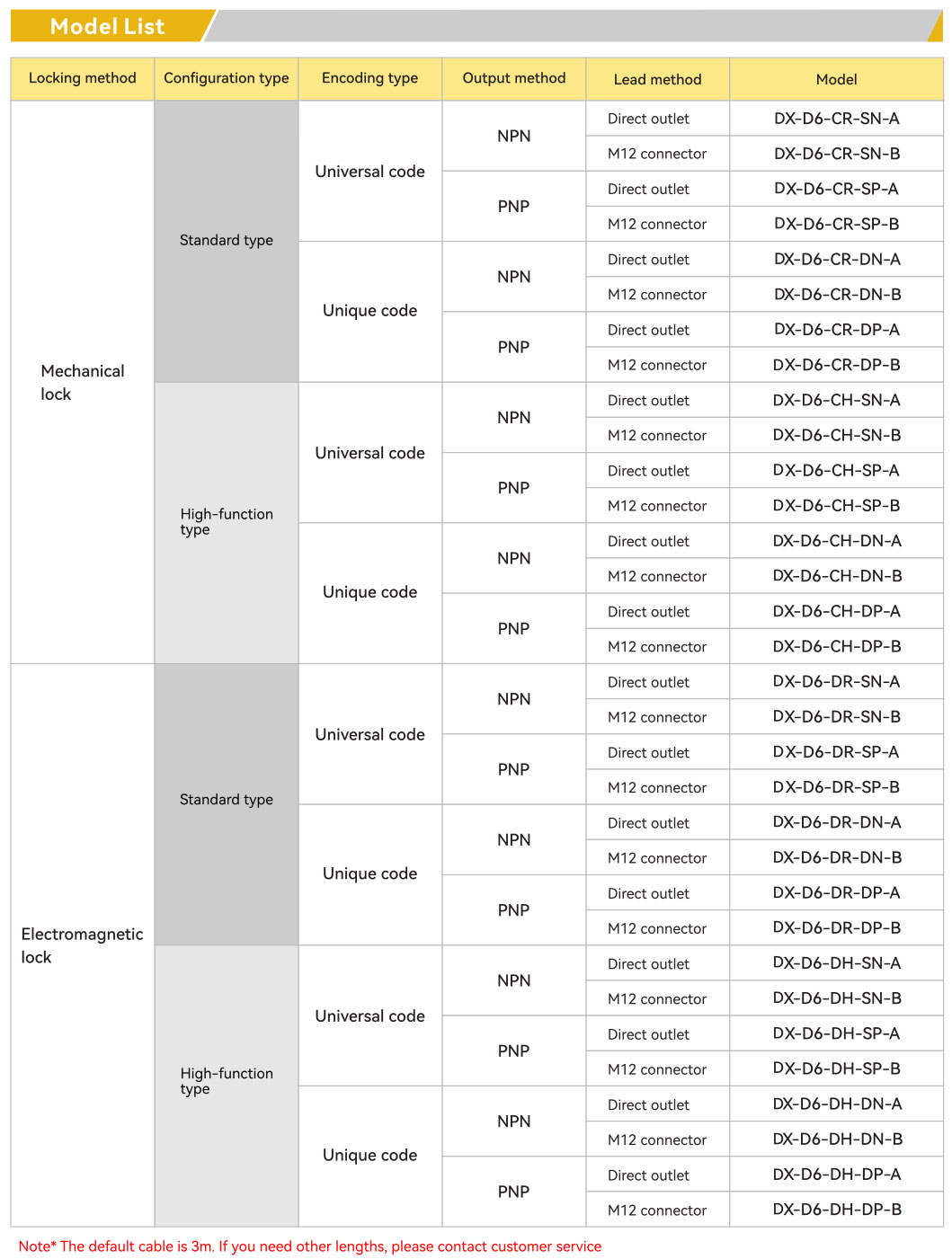
DX-D6 Series Safety Door Switch — Mechanical Locking and Electromagnetic Locking
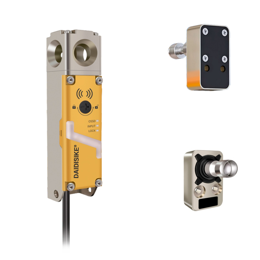
- All-metal structure: sturdy, safe and durable.
- Multiple functions: mechanical locking + electromagnetic locking with status monitoring.
- Coding methods: unique and universal coding available.
- Redundant dual output: prevents safety hazards from single-circuit failure.
- Cascaded connection: reduces PLC input points — up to 20 units in series.
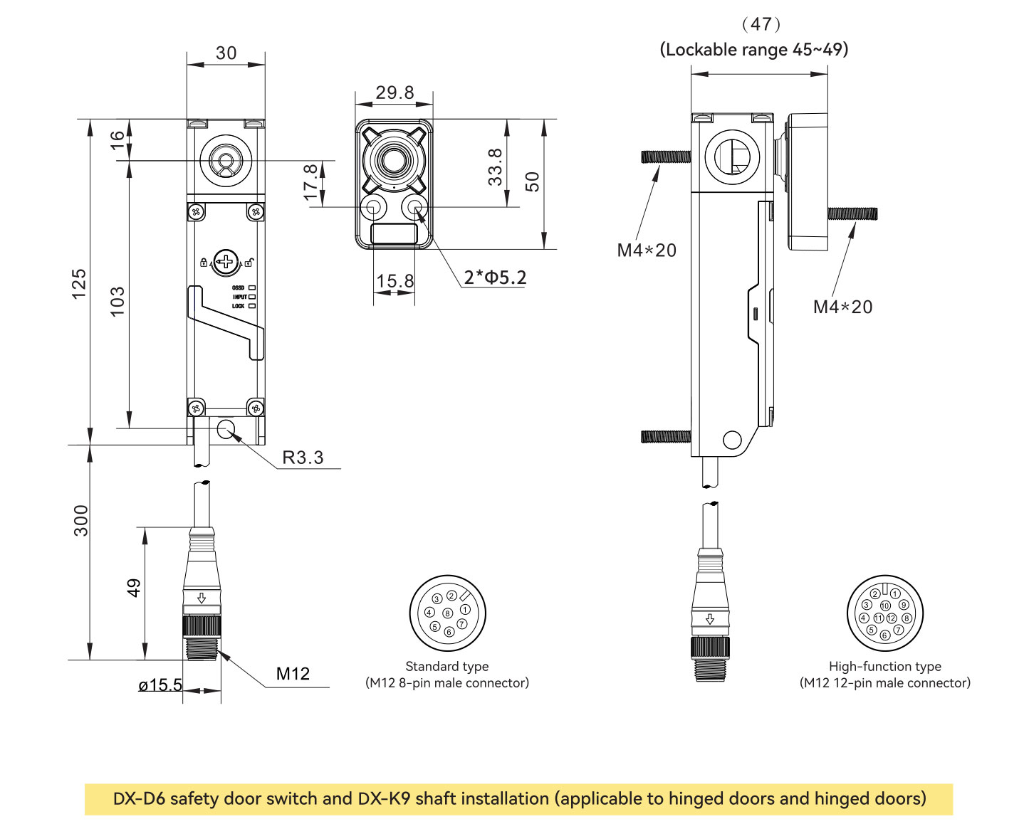
- Compact appearance: 30 × 30 mm cross-section.
- Flexible installation: mounts directly on aluminum frames ≤ 30 mm.
- Suitable for: security doors, security windows, isolated areas.
- Applications: automated production lines, robot cells, hazardous test areas.
- Forced safety output: at least 2 NC contacts; multiple auxiliary contact options.
Technical Parameters
| Parameter | Value |
|---|---|
| Standard | ISO 13849-1 (Category 4 / PLe); IEC/EN 60947-5-3 |
| Certification | CE |
| Locking method | Mechanical locking / Electromagnetic locking |
| Safety output | NPN ×2 / PNP ×2 |
| Response time | |
| Locked → Unlocked | 100 ms (working independently) |
| Unlocked → Locked | 100 ms (working independently) |
| Locking | |
| Holding force Fzh (locking force) | ≥ 2000 N |
| Latch engagement tolerance | ≤ 2 mm |
| Mechanical service life | > 1,000,000 cycles (door operating speed 1 m/s) |
| Operating frequency | 1 Hz |
| Minimum swing-door radius | ≥ 220 mm |
| Manual release / Manual unlock | Front, back |
| Cascade connection | Maximum 20 units |
| Control output (OSSD output) | |
| Output type | Transistor output × 2 |
| Maximum load current | ≤ 200 mA |
| Residual voltage (ON state) | ≤ 2.5 V @ 200 mA |
| Voltage in OFF state | ≤ 2 V @ 5 m cable |
| Leakage current | ≤ 0.5 mA |
| Maximum load capacitance | 2.2 µF |
| Load connection resistance | ≤ 2.5 Ω |
| AUX output (non-safety) | |
| Output type (diagnostic / auxiliary) | Transistor output |
| Number of outputs | 1 |
| Maximum load current | 50 mA |
| Residual voltage (ON state) | ≤ 2.5 V @ 50 mA |
| External input (leakage current) | |
| Safety inputs | 1.5 mA × 2 |
| Reset / EDM input | ≈ 10 mA × 1 |
| Lock-control input | ≈ 10 mA × 1 |
| Power supply | |
| Operating voltage | DC 24 V ± 15% |
| Rated power | 4.6 W (no-load) |
| Protection functions | Safety break protection, current limiting, overload, overvoltage, overheating (stop & restart), reverse polarity, transient noise, failure-pulse protection |
| Environmental resistance | |
| Enclosure protection rating (IP code) | IP65 |
| Operating ambient temperature | −20 °C to +55 °C (no freezing) |
| Storage ambient temperature | −25 °C to +70 °C (no freezing) |
| Operating ambient humidity | 5 % – 95 %RH |
| Storage ambient humidity | 5 % – 95 %RH |
| Vibration resistance | 10 – 55 Hz, double amplitude 2.0 mm, 5 min in X / Y / Z (IEC 60947-5-3) |
| Shock resistance | 30 g, 6 times in X / Y / Z (IEC 60947-5-3) |
| Risk time (response time to hazard) | 100 ms |
| Start-up time | 3.5 s |
| Materials | Nylon / Zinc alloy / Stainless steel |
1) Positioning & Use Cases
DX-D6 is an industrial guard door interlock with electromagnetic locking, built for machine tools, robot cells, packaging / assembly lines, and high-risk isolation zones. It keeps the door locked while hazards remain and permits opening only after a verified safe state.
2) Key Engineering Advantages
- Dual safety mechanism: mechanical interlocking + electromagnetic locking prevents premature access.
- Safety-chain ready: compatible with safety relays / PLCs, dual-channel monitoring.
- Mis-operation resistant: door / lock status indication and actuator-presence detection minimize false releases.
- Ruggedized for industry: sealed housing, vibration-resistant, oil & dust tolerant; heavy-duty mounting options.
- Service-friendly: front access wiring, clear terminal markings and intuitive LEDs shorten commissioning time.
- Standards-driven: designed against IEC/EN 60947-5-1 / -3 and GB 14048.5-2017 (see certificates & test reports).
- System solution: integrates with DAIDISIKE light curtains, E-stops, door sensors and safety relays.
3) Typical Control Logic
- Interlock + Stop: open / unsafe door → safety relay opens → machine enters safe stop.
- Unlock release: only after safe-state confirmation + enable signal → magnet releases → door can open.
- Re-start prevention: opening the door breaks the safety circuit; re-start requires closing the door and a deliberate reset.
4) Detailed Specifications
Housing & Mechanics
- Material: zinc-alloy main body, stainless-steel actuator
- Mounting: left / right, horizontal / vertical
- Door type: hinged / sliding; optional heavy-duty kits
- Actuator: straight / adjustable / heavy-duty
- Cross-section: 30 × 30 mm
Locking Performance
- Locking type: power-to-lock / power-to-release options
- Holding force: ≥ 2000 N
- Mechanical life: > 1,000,000 cycles
- Door operating speed: 1 m/s
Sensing & Outputs
- Door position: monitored via OSSD
- Lock status: monitored via AUX output
- Safety level: PLe / Cat.4 (ISO 13849-1)
- Electrical rating: DC 24 V, OSSD ≤ 200 mA
- Response time: 100 ms
Electrical
- Supply: 24 VDC ± 15 %
- Rated power: 4.6 W no-load
- Interface: terminal block / M12 / cable
- Protections: over-current, overload, overvoltage, reverse polarity, transient noise
Environment
- IP rating: IP65
- Operating temp: −20 °C to +55 °C
- Humidity: 5 – 95 %RH
- Vibration: 10-55 Hz, 2.0 mm amplitude
- Shock: 30 g, 6 times each axis
HMI & Service
- LEDs: Power / Door / Lock / Fault
- Mechanical override: emergency / maintenance release from front & back
- Reset mode: manual or automatic; external reset terminal
Standards & Compliance
- ISO 13849-1, IEC/EN 60947-5-3, GB 14048.5-2017
- CE, RoHS
- Traceability via nameplate / QR / serial number
Kits & Options
- In-box: actuator, screws, quick-start guide
- Options: adjustable striker, reinforced brackets, cable extensions, heating accessory
5) Selection & Integration Tips
- Choose locking logic (power-to-lock vs. power-to-release) based on machine inertia and risk category.
- Match output type with safety relay / PLC inputs (NPN / PNP / dry contact / OSSD); wire both channels independently.
- Route cables away from power lines; use shielded cabling and proper grounding; consider a dedicated 24 VDC supply.
- Validate stopping time and compute safety distance per ISO 13855; document periodic functional tests.
6) Installation & Maintenance
- Align the actuator with the lock head; ensure recommended insertion depth and use anti-loosening hardware.
- Verify terminal mapping and LED states on first power-up; test door / lock contacts and reset behavior.
- Establish inspection intervals for wear, alignment and contamination; maintain logs as part of the safety lifecycle.
Frequently Asked Questions
Does the DX-D6 safety door switch meet ISO 13849-1 and ISO 14119?
Yes. The DX-D6 is designed to ISO 13849-1 Category 4 / PLe and IEC/EN 60947-5-3, the relevant standards for guard-locking interlock devices used in machinery safeguarding. It uses redundant dual-channel OSSD outputs with status monitoring so a single fault does not lead to loss of the safety function, supporting power-to-lock and power-to-release guard-locking logic.
How much holding force does the DX-D6 guard locking switch provide?
The DX-D6 delivers a holding force (Fzh) of ≥ 2000 N, keeping the guard door locked while a hazard such as machine inertia or run-down motion remains. The mechanical latch has an engagement tolerance ≤ 2 mm and a rated mechanical life over 1,000,000 cycles at a 1 m/s door operating speed, suiting demanding machine-tool and robot-cell duty.
What is coded actuation and can DX-D6 units be cascaded?
The DX-D6 supports both unique and universal coding, so high-coded versions resist defeat by spare actuators per ISO 14119. Up to 20 units can be cascaded in series on one safety circuit, reducing PLC input points across multiple guard doors while keeping each door individually monitored through the OSSD safety chain.
Can the DX-D6 replace a Euchner, Pilz or SICK RFID safety interlock?
In most cases yes. The DX-D6 is an all-metal 30 × 30 mm guard-locking switch with OSSD transistor outputs, DC 24 V supply and IP65 rating, so it integrates with the same safety relays and PLCs as Euchner, Pilz, SICK or Schmersal interlocks. Match the coding level, locking principle and actuator orientation to the unit being replaced.
What ingress protection and environmental range does the DX-D6 have?
The DX-D6 is rated IP65 with a nylon, zinc-alloy and stainless-steel construction, an operating temperature of −20 °C to +55 °C and 5–95 %RH humidity. It withstands 10–55 Hz vibration at 2.0 mm amplitude and 30 g shock per IEC 60947-5-3, making it suitable for machine tools, robotic cells and isolated hazardous areas.
Specs reviewed by Engineer Cai, Senior Application Engineer. CE & RoHS compliant — see certificates.
Safety Light Curtain — Customer Cases
Real installations from DAIDISIKE clients. Click any case to view in full. Filter by scenario to quickly find a similar setup.